These photographs are from the Cambridge-Somerville area in Massachusetts, a mile away from where one of the Boston bombers lived.
I lived in this area for a year as an international student from India and unknowingly shared a temporal and physical landscape with Tamerlan Tsarnaev. But did I also share a mental landscape?
I too was an immigrant there. I too was a student. I too felt alienated at times, and did not always comprehend my surroundings. These photographs were my attempt to come to terms with my environment. Unfortunately Tamerlan chose a different form of self-expression.
By acknowledging that we had something in common, however fleeting, I now hope to make some sense of the incomprehensible destruction in a place that eventually became very dear to me – a place that will always remain a second home.
Forty of the 2nd year students of the University School of Architecture and Planning (USAP) who were a part of the architectural design studio exercise with Abhishek Bij, Malini Kochupillai, Kanishka Prasad and me, completed the full-scale structures for their college festival. A big thank you to everyone who was a part of this!
You can read a detailed description of the project in this previous post.
A photograph I shot was on the cover of this month’s issue of Domus India (March, 2013).
The Cover Photograph
I had shot this at 400 ISO with my Nikon D 7000, and what was published was a fairly tight crop of the original image (below). Another, less cropped version of the same photograph also appeared in the article on the Museum of Tribal Heritage in Bhopal designed by Kamath Design Studio in the same issue.
The Original Image
It must have taken some very skilled raw editing to get an acceptable cover image out of something shot with what is essentially an amateur camera at what is not a low ISO setting. This is definitely not something I’ve been able to achieve with the Nikon ViewNX2 software that comes bundled with the camera. Since a majority of the photographs featured in the article were shot by me with this camera, I think I might be better off investing in a good raw converter instead of a Nikon D600 which I have been eyeing ever since its release.
My camera geekiness aside, this article on the Museum in Domus has given me a lot to think about, both as an architect closely involved with the design of the building, and as the photographer who shot most of the images seen of the building. But before I go further, I must confess that I have not yet read anything by Susan Sontag, not read On Photography, nor read anything else of significance on the role of photography in architecture and the media. What I write here is a lay person’s opinion based on a single experience –
I had started working on the Museum of Tribal Heritage when I was still doing my bachelor’s degree in architecture. It was very exciting to be working on this project because it was the first time I was applying my newly acquired knowledge of architecture in a professional setting. Preparing a setting-out plan of the complex, interlinked circular and rectilinear shapes taught me the need for accuracy and discipline in drafting and dimensioning a drawing.
I was also responsible for preparing a 3D model of the building which was used in presentations and discussions with the various stakeholders in the project.
External Views from the 3D ModelAn Interior View of the Introduction Gallery from the 3D Model
Despite being involved in the project from its outset, I was not able to travel from Delhi (where I was studying) to the site in Bhopal until after I finished college some two years later. But when I did visit the site, it was quite amazing to see the actual building. What made this experience especially surreal was the fact that the site engineer drove us in his car straight into what was the main visitor’s (pedestrian) circulation spine of the museum. The building was bigger than I had imagined. And yet, when I got out of the car and walked around, it seemed to have a very human scale – a scale of a village street, not the scale one usually associates with a museum building.
The circulation spine where I drove in a car on my first visit to the site.
After walking around the building, I soon got my bearings and started observing deviations from the plan and defects in construction, like any architect would. The building eventually took over five years and many more site visits to build, and the museum is still to formally open as of March, 2013.
When we were contacted by Domus India about their wanting to feature the project in their magazine, we were very excited by the idea. Like most architectural publications around the world today, the team at Domus asked us, as the architects of the building, to provide them with images for the article. What we gave them was a photographic “walk-through” of the building with details of where in the building each photograph was shot from, and what the photograph showed. Other than basic project drawings, this was all the information on the project that the Mumbai-based team writing the article had. Even as someone so closely involved with the design, having prepared its setting out plan and 3D model; actually experiencing the building physically and spatially gave me a completely new perspective on its design. I was therefore fascinated by the article on the Museum that appeared in Domus titled “Debating Tactile Engagements” when no one from the magazine had seen the building other than through the photographic images we had supplied them. The article goes on to talk about the scale of the building, the delicacy of the steel structure supporting large spans, the way the building negotiates the terrain of the site and engages with the local climate. It is understandable that time and financial constraints make it impossible for every architectural critic to visit every building they write about. But as an architect who respects the opinions of serious critics of design, it makes me wonder if I should design for the user or design for the camera in an age where pixels are equal to perception, where bits can travel across the planet but bricks stubbornly stay rooted in walls, where ones geographic location is immaterial but “ecological footprint” is supposed to matter, where global weather data is available at a keystroke but the sound of subtly directed rain water is lost in the din of esoteric discussions on design philosophy.
Today I’m going to talk about the use of computation in architecture. A lot has been said about computation and its role in architecture since the early 1980s. Today, virtually any architectural practice uses computers in some form or the other. But it is not just architecture. Today, virtually any profession uses a computer in some form or the other.
So what is it that computation offers?
I am sure that all of you have wished that there was an “UNDO” command that you could use when you have made a mistake while building a model for your design studio. But of course, there is no “UNDO” command outside the computer. Have you ever wondered why?
In order to understand why this is so, I am going to have to briefly switch from architecture to thermodynamics. I am sure that all of you are familiar with the Second Law of Thermodynamics from your physics class in school. One version of this law states that “The disorder in a closed system will always increase.”
What this means is that you are not going to see spilt milk spontaneously gather back into a glass. You cannot “UNDO” the spilling of milk. And some people argue that the Second Law is what defines the direction in which time flows.
But how is it that a computer allows us to “UNDO” things? How is a plant able to grow with soil, water and sunlight? How does a machine make something as complex as a computer in the first place? These are all examples of more order being made from less order.
Well, there is a very convenient loophole to the Second Law. If you add energy to a system then you can increase order. The addition of energy from outside means that the system is no longer closed, but then no system is ever completely closed anyway.
The addition of energy therefore frees us from the second law. Plugging a Xerox machine into a socket allows it to make copies. Light falling on a leaf enables a plant to grow through photosynthesis and ultimately reproduce. Powering up a computer lets it “UNDO.”
So the way a system uses energy determines its relationship to disorder. On this basis, one can think of four different “Realms” or “Paradigms” – the mineral realm, where disorder always increases; the biological realm where order is propagated; the mechanical realm where disorder is controlled and order is created; and the digital realm where there is no disorder.
So what does the digital realm, with no disorder, offer the architecture?
It offers a clean slate as the starting screen of any CAD software will show you. It offers a void with no disorder where you are free to design without any encumbrances. You are free to do what you want.
While a blank sheet of paper is a two dimensional “void,” the computer offers a three dimensional blank slate. In addition to this, the computer offers the ability to process large amounts of information quickly.
If we think of “complexity” as the amount of information required to describe an object or phenomenon, then we can say that the information processing power of a computer allows architects to deal with complexity.
A project done by the studio that made use of what the digital realm offers is the Gateway to the JSPL power plant in Chhattisgarh, built in 2006. The form of this gateway creates a dialogue between local tribal geometries and industrial technology. The design development was undertaken through physical and 3D digital modelling with the geometric information of the digital model being used to create CNC pre-fabricated components that were assembled on site.
There was therefore a seamless flow of information from the digital model to the fabrication of the components by computer controlled machines which used data directly from the model. This allowed for very high precision and the coming together of the pre-fabricated parts smoothly on site in spite of the complexity of the form.
But if we re-visit the construction process of the gateway, we see that the digital realm, from which the design and the computer controlled fabrication comes, must eventually interact with the mineral, biological and mechanical realms. You see this in the critical step of fixing the structure to the footing in the ground. Had there been any mistake in the foundations, and had it not matched the digitally fabricated structure, there would have been no “UNDO.”
Another factor not immediately apparent is the amount of energy needed to manufacture the steel needed for the digital fabrication process. This energy is needed to create a material which is completely homogenous and uniform. The energy is needed to fuel machines which remove the disorder present in the mineral realm.
The removal of disorder from materials is needed when designing in the digital realm because design in the digital realm always begins with a perfectly ordered blank slate. And as long as one stays in the digital realm, there is no way of interacting with the disorder of other realms. While the digital design process can generate complexity, it cannot deal with disorder.
This is not a new thing in architecture. Historically, what has differentiated the architect from the master builder has been that the architect works on paper, in a space free of disorder. But the power of digital technologies available to architects today highlights the issue like never before.
The most obvious way to overcome this is to NOT start the design process in the digital realm – which is what I did in this small experiment with bamboo. Instead of starting with a blank slate, I started by scanning a piece of bamboo on a simple flatbed scanner, thereby digitizing disorder.
I used the scans of two pieces of bamboo to create digital models of them. Because I did not start with a blank slate but instead started by digitizing the disorder of the irregularly shaped bamboo, the computer had no problem in dealing with the complexity of its shape.
I then designed a joint between the two pieces where the angle is exactly 60 degrees. This joint was cut in the bamboo using a computer controlled router and the two pieces of bamboo were then tied with rope by hand. The computer was therefore able to negotiate the complexity of disorder and impose the order of a 60 degree joint on the bamboo.
But humans are much better at dealing with disorder. So can computers and humans collaborate with each other to build complex designs while negotiating disorder?
The first attempt at answering this question was the Parametric Pavilion project. For this project a parametric model was made to create a family of bamboo pavilions that can be built cheaply and quickly for a variety of functions. The parametric model can be manipulated to generate new forms based on programmatic requirements and site conditions. The parametric model outputs dimensioned drawings for construction on site where craftsmen negotiate the disorder inherent in bamboo with the computer generated dimensions.
The hyperbolic paraboloid shape of the pavilion as well as the gateway is part of a larger group of shapes known as ruled surfaces – surfaces that can be made from straight lines.
This geometry is such that the structure can be built using only length dimensions and there is no need to measure angles, curvatures, areas, etc. Linear measurements are the easiest to measure, requiring only a measuring tape to be placed against a piece of bamboo and lengths marked. The use of linear measurements minimizes the chances of errors and also makes the work of the craftsmen on site easier.
But can this technique of linear measurements be extended to more complex geometry?
If you take a flexible member and reduce the distance between its end points then it will curve. If you have a network of such members intersecting each other, then you can obtain virtually any surface you like. And this is nothing but weaving.
The Nest Roof is an on-going project where we are using weaving to construct a complex computer generated surface from bamboo through linear measurements alone.
The shape of the roof was the result of an algorithmic form-finding process resulting in a funicular shell structure. The shape of this shell was dictated by the plan form of the building.
It was decided to weave this shape out of bamboo as a reticulated shell structure. A reticulated shell is a doubly curved structure made from intersecting members of a flexible material. The flexibility of bamboo increases as it becomes thinner, but as it becomes thinner it also becomes weaker. The less a bamboo member has to curve, the thicker and stronger it can be. So an algorithm was created to find paths of minimal curvature along the shell surface along which to weave the bamboo.
The use of this algorithm allowed us to have 4” dia half-round bamboo members arranged in 6 layers to achieve a beam-depth of 2’.
In order to construct this, drawings were made where the lengths of bamboo between each intersection were given for each step of the weaving sequence. Since these lengths were more than the linear distance between the end points of each member, the desired curvature was achieved.
The craftsmen of site could therefore build this structurally optimized reticulated shell structure using only linear measurements. The craftsmen themselves could then focus on negotiating the disorder inherent in the bamboo such as joining two pieces of bamboo to create a continuous structural member, and place spacers of different sizes to absorb variations in the size of bamboo.
So, in this project the computer deals with the ordered aspect of design while human craftsmen deal with disorder, and, as architects we found an efficient way to transfer information from the computer to the craftsmen through linear measurements and weaving.
Some months ago I found an article about an exhibition titled The Machine organized by the Design Hub Limburg that includes a fascinating tool for designers. This tool is the result of a project called Computer Augmented Craft, which, the head of the project, Christian Feiberg, says, “is an attempt to utilise advanced technologies without sacrificing the unique qualities of craftsmanship.” The tool combines a set of sensors with Arduino and an interface created in Processing to enable a designer to have a real-time digital model of an artefact that they are physically producing. The software interface also provides “suggestions” at each step of construction to enable the designer to conform to an initial set of parameters or choose not to do so. The following video shows the system in use –
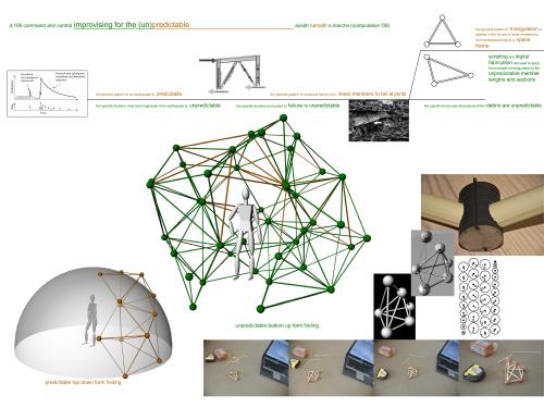
Reading about this tool and the exhibition reminded me of a student project I had done in the Command & Control design studio with Simon Kim, Skylar Tibbits and Juhong Park in 2009 at MIT. My project in this studio (focusing on using scripting as a design tool) included a script that created mass-customised joints for a post-earthquake shelter constructed as an irregular space frame out of found rubble. In this project the script did not dictate the form of the structure but only created fabrication data for a mass-customised joint component after the human builder had decided what member to use (from the post-earthquake rubble at hand) and where in the structure to place it. The script overcame the unpredictability of the materials at hand by taking inputs (on the length of a found member that the builder wanted to attach at a particular location) incrementally. The resulting digital model grew in tandem with the physical model allowing the builder to take independent design decisions while the script recorded the builder’s design moves and output fabrication data for the joint components needed at each step. If the builder got stuck and was unable to triangulate the space frame at any point then the script would suggest a method to triangulate.
My poster from the Command & Control studio in 2009. The green members in the main figure denote “found” members while the red members denote those added by the script to triangulate the space frame.
Re-visiting this old student project in the light of the “The Machine” exhibition resulted in a project for the Patterns and Performance 2nd year, B.Arch design studio I am teaching with Abhishek Bij at the University School of Architecture and Planning (USAP). For this exercise we collaborated with the studio taught by Malini Kochupillai and Kanishk Prasad to design a learning space for a group of 20 students. I wrote a new version of the script I had coded for my Command & Control project for use by the students. The new script did not focus on the joints and instead was designed for the specific design problem given to the students for this exercise – the design of a learning space housing 15 to 20 people using a space frame structure constructed from available members of irregular lengths. The students were given tutorials on space frames and introduced to the script written for them. They were introduced to different forms of education and their spatial implications – both interior and exterior.
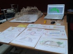
After this, the students began their designs in groups of four, constructing 1:10 or 1:20 scale physical models of their structures and simultaneously using the script to “grow” a 3D computer model. This studio exercise exposed the students to the advantages and disadvantages of physical versus digital design processes, issues of error and tolerance in design and construction, the importance of improvisation and contingency and its incorporation into the design process.
The physical and digital models growing side-by-side in the studio.
While my initial script written for the Command & Control studio focused on creating digitally fabricated joints, the script written for the USAP students included a panelization tool. This tool allowed the students to choose where to place panels on the space frame and have the script add these panels to the 3D model and also provide fabrication data for the panels so that they could be printed as a 2D triangle, cut and be added to the physical model.
Some student projects from the studio.
The next step in the design studio will be to use what one has learnt constructing models and build a full-scale bamboo space frame as a learning space on the college campus. Observing the students work on the models I have updated the script for the full-scale structure. The updated script calculates the centre of gravity of the structure at each iteration of the design and construction process and gives a warning if the structure is likely to topple over without support. The reason for the addition of this feature in the script is that while it is easy to support a table-top model by hand if it is toppling over, this is not a trivial task during full-scale construction. This feature will allow the script to inform the steps in the physical construction process, while design decisions in response to space and material are taken in the physical world and fed into the script. Such a design process will aid in bringing the digital and physical worlds closer together to create a digitally augmented, craft-based, design process.
The latest version of the script written for the studio is given below (please note that there are still some bugs in calculating the centre of gravity) –
Option Explicit
‘Script written by <Ayodh Kamath>
‘Script version 18 November 2012 12:02:10
Call Main()
Sub Main()
Dim strStart, arrExist
Dim arrDots, arrLines, strExit
Dim i
strStart = Rhino.GetString(“Start from scratch [S], use existing geometry[G], triangulate with a single member [T], panelize [P], or exit[X]?”,,Array(“S”,”G”,”T”,”P”,”X”))
Call Rhino.ZoomExtents(,True)
arrDots = Rhino.GetObjects(“Please drag a selection box around the existing text dot points and ‘Click+Cntrl’ to de-select any unwanted geometry.”,8192)
arrLines = Rhino.GetObjects(“Please drag a selection box around the existing lines and ‘Click+Cntrl’ to de-select any unwanted geometry.”,4)
arrDots = Sort(arrDots)
strExit = “A”
Do
arrDots = Tetrahedron(arrDots, arrLines)
Call Rhino.UnselectAllObjects
strExit = Rhino.GetString(“Make another tetrahedron [A], or exit [X]?”,”A”, Array(“A”,”X”))
Loop While strExit <> “X”
ElseIf strStart = “T” Then
Call Triangulate(arrLines,arrDots)
ElseIf strStart = “P” Then
Call Panelize()
End If
Loop While strStart <> “X”
End Sub
Function Triangle(ByRef arrLines)
Dim dblLt1, dblLt2, dblLt3
Dim strLn0, strLn1, strLn2
Dim strDotP0, strDotP1, strDotP2a, strDotP2b, strDotP2
Dim strTempCirc1, strTempCirc2
Dim arrInt, arrIntPt0, arrIntPt1, strPt0, strPt1, strPt2
Dim strChoice, blnLoop
Call Rhino.DeleteObject(strLn0)
Call Rhino.DeleteObject(strDotP0)
Call Rhino.DeleteObject(strDotP1)
Call Rhino.MessageBox(“The member lengths can not be triangulated. Please try a different set of members.”)
End If
Loop
End Function
Function Sort(arrTxtDot)
Dim strMin, blnSwap
Dim i, j, k
Do
blnSwap = False
For i = 1 To UBound(arrTxtDot)
If Rhino.TextDotText(arrTxtDot(i-1)) > Rhino.TextDotText(arrTxtDot(i)) Then
ReDim arrInPts(2)
ReDim arrTempDots(2)
ReDim arrInLts(2)
ReDim arrTempSphs(2)
Dim arrIntSrf, strJoinCrv, arrIntCrvSrf
ReDim arrIntDots(1)
Dim strChoice, arrIntPt
Dim i, j
Dim blnLoop
Dim intPtNum
Dim intCGChoice
ReDim arrTempLines(2)
Dim intLineCount
Dim blnGoal, arrGoalPt
blnLoop = 0
Do While blnLoop = 0
blnGoal = Rhino.GetString(“Select a goal point?”,,Array(“Y”,”N”))
arrInLts(i) = Rhino.GetReal(“Enter member length at this node:”)
arrTempSphs(i) = Rhino.AddSphere(arrInPts(i),arrInLts(i))
Call Rhino.ZoomExtents(,True)
Call Rhino.DeleteObject(arrTempDots(0))
Call Rhino.DeleteObject(arrTempDots(1))
Call Rhino.DeleteObject(arrTempSphs(0))
Call Rhino.DeleteObject(arrTempSphs(1))
blnLoop = 0
Call Rhino.MessageBox(“The member lengths can not be triangulated. Please try a different set of members.”)
Exit For
strChoice = Rhino.GetString(“Point IntA[A] or point IntB[B]?”,”A”, Array(“A”,”B”))
If strChoice = “A” Then
arrIntPt = arrIntCrvSrf(0,1)
ElseIf strChoice = “B” Then
arrIntPt = arrIntCrvSrf(1,1)
End If
Else
Call Rhino.DeleteObjects(arrTempDots)
Call Rhino.DeleteObjects(arrTempSphs)
Call Rhino.DeleteObject(strJoinCrv)
blnLoop = 0
Call Rhino.MessageBox(“The member lengths can not be triangulated. Please try a different set of members.”)
Exit For
Function JoinCurve(arrCrvs)
‘takes the two dimensional array resulting from a SurfaceSurfaceIntersection command and returns the string identifier of the joined intersection segments
Dim strStart
Dim strDot1, strDot2, strDot3
ReDim arrPts(2)
Dim strSrf
ReDim arrEdges(2)
ReDim arrDgs(2)
Dim arrTempDiv
ReDim strDots(2)
Dim intMsg, arrFlat, arrFlatOrPt, arrBox
strDot1 = Rhino.GetObject(“Select first point”,8192)
Call Rhino.SelectObject(strDot1)
strDot2 = Rhino.GetObject(“Select second point”,8192)
Call Rhino.SelectObject(strDot2)
strDot3 = Rhino.GetObject(“Select third point”,8192)
Call Rhino.SelectObject(strDot3)
Function RhinoUnrollSurface(strSurface, arrCurves, blnExplode, blnLabels)
‘ Default return value
RhinoUnrollSurface = Null
‘ For speed, turn of screen redrawing
Call Rhino.EnableRedraw(False)
‘ Save any selected objects
Dim arrSaved : arrSaved = Rhino.SelectedObjects
‘ Unselect all objects
Rhino.UnSelectAllObjects
‘ Select the surface to unroll
Rhino.SelectObject strSurface
‘ Format curve string
Dim i : i = 0
Dim strCurves : strCurves = ” _Enter”
If IsArray(arrCurves) Then
strCurves = “”
For i = 0 To UBound(arrCurves)
strCurves = strCurves & ” _SelId ” & arrCurves(i)
Next
strCurves = strCurves & ” _Enter”
End If
‘ Format explode string
Dim strExplode : strExplode = ” _Explode=_Yes”
If (blnExplode = False) Then strExplode = ” _Explode=_No”
‘ Format labels string
Dim strLabels : strLabels = ” _Labels=_No”
If (blnLabels = True) Then strLabels = ” _Labels=_Yes”
‘ Script the command
Dim strCommand : strCommand = “_-UnrollSrf” & strExplode & strLabels & strCurves
Call Rhino.Command(strCommand, 0)
‘ Return the results
RhinoUnrollSurface = Rhino.LastCreatedObjects
‘ Unselect all objects
Rhino.UnSelectAllObjects
‘ If any objects were selected before calling
‘ this function, re-select them
If IsArray(arrSaved) Then Rhino.SelectObjects(arrSaved)
‘ Don’t forget to turn redrawing back on
Call Rhino.EnableRedraw(True)
End Function
Function CG(arrDots, ByRef arrLines)
ReDim arrDotPts(UBound(arrDots))
Dim dblSumLength, arrMidPt
Dim dblX, dblY, dblZ, dblLength
Dim i
ReDim arrMemCGPt(2)
ReDim arrJtCGPt(2)
ReDim arrCGPt(2)
Dim strTempCGPt, strTempCGLine, intCount
intCount = 0
ReDim arrBasePts(intCount)
Dim arrSortBasePts, strBaseCrv, intInside, arrCGBasePt
Dim intChoice
Dim dblMemDens, dblJtWt
dblMemDens = 1 ‘average bamboo density assumed to be 1kg/running meter = 1g/running mm
dblJtWt = 2000 ‘average weight per joint assumed to be 2kg = 2000g
Dim intPolyCount, intPtCount, intInOut
Dim i, j
Dim arrTempPoly, strTempPoly
Dim dblDist, dblMinDist, intMinPt, bolMin
Dim dblParam, arrClsPt
Dim arrTempPts
Dim arrJoin
intPtCount = 0
intPolyCount = 2
bolMin = 0
ReDim arrPts(intPtCount)
ReDim arrBasePts(intPolyCount)
ReDim arrBaseLns(intPolyCount)
It has been a long time since I have done anything photographic that I felt like posting, my last time being this post over two years ago.
A few days ago a friend of mine pointed me to this article about a set of images juxtaposing archival photographs from World War II with identical images shot in the same locations today. I found the idea very interesting and my mind began to speculate how the same people in the same situation may have behaved in the same space today and I wished the people from the archival photographs would somehow engage with the contemporary spaces in a more direct way.
Turning the idea around, I began to think about some photographs I had taken at Lodhi Gardens last month. Here were contemporary people interacting with relics from the past. What if the spaces of the past could mould themselves around the actions of these contemporary individuals? I have posted the images resulting from these speculations in this set on Flickr.
After some delays in the project, construction on the woven bamboocrete “Ghosla” (nest) roof has finally begun. The video below shows how the weaving process enables a team of traditional bamboo craftsmen to easily construct the digitally form-found, double-curved, funicular shell using only linear measurements read out to them by the contractor. The drawing provided by Kamath Design Studio to the contractor is a plan consisting of linear dimensions along each bamboo member where that member intersects other members. The drawing also communicates the weaving scheme, that is, whether a member goes above or below another member when they intersect. Our studio provided the height above ground at each intersection to verify that the bamboo members are curving as desired, and that the shape of the shell conforms to the digitally form-found funicular shape.
While a 1:50 scale construction model of this roof had been built using the same drawing set to test the concept of weaving a complex curved surface using only linear dimensional information, the idea was so far untested at full scale.
I had outlined the concept of using weaving to build complex digitally modeled surfaces using manual methods of construction in this earlier post.
The Kamath Design Studio website is now live at www.kamathdesign.org after many months of rewarding work with Rajesh Advani of ArchiShots. The site uses Google maps to interactively display the work of the studio in its real context, as it has been built, along with slide shows and short write-ups on projects. Currently the site features a few key projects outlining the trajectory of the studio over the last 30 odd years. We will be adding more projects from the past as well as new projects as they are completed, so please do keep checking the site for updates. The site also features a record of publications featuring the work of the studio for reference.
An old friend of mine directed me to this talk which describes a very interesting methodology of building with bamboo using a mixture of traditional craft techniques and digital design that involves reverse engineering scale models.


.jpg&w=459&h=301&zc=2)